Accessible Shopping Cart
A class I took at McMaster, Mechanical Engineering Design II, required groups of 4 or 5 students to identify an area where a new device might be needed. It was a pretty broad task that allowed a lot of room for creativity. My group decided early on we wanted to create something that would help the elderly regain their independence. We settled on the idea of a portable shopping cart that allowed the user to reach their groceries without needing to bend down and to take their groceries home with them without needing to unload all bags individually into their car.
My role in the group was mainly design. My colleagues and I decided what we wanted the cart to do, what general dimensions we wanted, and what mechanical advantage we wanted from the pulleys. I did all the CAD work in Autodesk Inventor as well as any on-the-fly design decisions. I picked the material, tubing sizes, fasteners, bend radii of the tubing, hole locations, and any commercial off the shelf (COTS) items such as the caster wheel and crank handle. I also designed the cart clips and guides for the basket. My colleagues did all the hand calculations, and I verified they made sense with finite element analysis (FEA) in Inventor
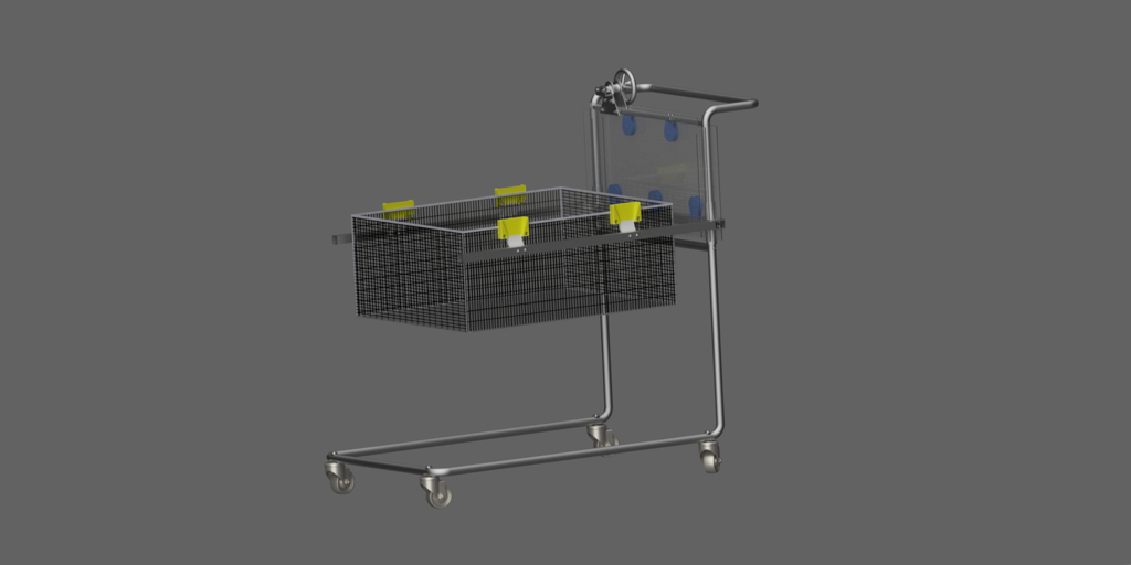
We designed the cart you see here. All of the tubular members, both round and square, will be made out of aluminum 6061-T6 because it is both strong and lightweight. Our cart has a main carriage that moves up and down. To use our cart, simply rotate the crank handle to lift the carriage. The cart can be pushed into the vehicle such that the bottom of the cart slides under the car and the basket goes into the trunk. The user then lowers the basket by releasing the handle and letting the rotary damper slow the descent. When the carriage is fully lowered, the clips will be free of the guides on the basket and the cart can be pulled away and disassembled into its 2 main pieces. To pick the basket back up again, raise the carriage and position the cart so that the clips are above the guides and then lower the carriage. The clips are compliant so they will flex and then snap into place once they are inline with the bottom of the clip guides.
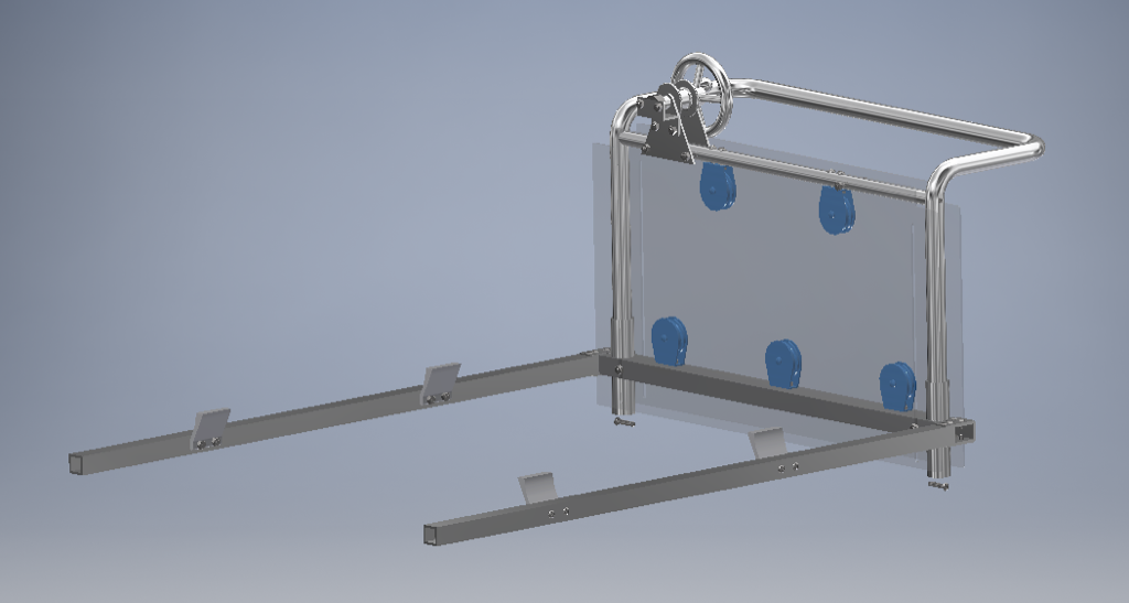
The pulley system has 5 pulleys, a spool, a crank handle, and uses aircraft cable to achieve a mechanical advantage of 30 when lifting the basket. This means that for every 1 lb of force you would apply to the crank handle, the crossbar of the carriage will experience 30 lbs of force and will transfer that along the carriage arms to the basket. So to lift 30 lbs of groceries in the basket, you only need to use 1lb of force.
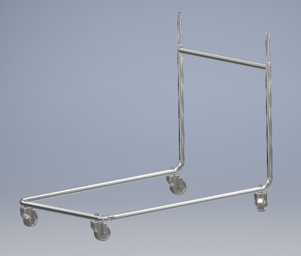
The cart comes apart into 2 main pieces. The idea is that when you have dropped the basket off in the trunk of your vehicle, you can then lift off the top half of the cart and it will detach easily from the base. These 2 components are light and small enough to be easily picked up and stored in the back seat or trunk of the vehicle so that it can be taken anywhere.
This is the carriage assembly. The round tubes on the crossbar act as bushings and the upright tube sections of the top half are inserted into these. The whole carriage moves freely up and down. Ideally, this specific component would be redesigned because it introduces a lot of friction and the possibility of jamming.
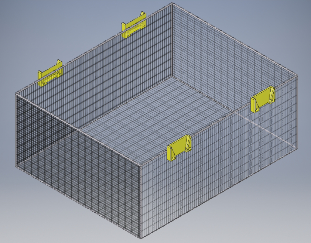
This is the basket of the cart. It would likely be made of galvanized steel because it needs to be strong to carry our estimated 50lbs of groceries and it needs to not rust when taken outside in the rain.
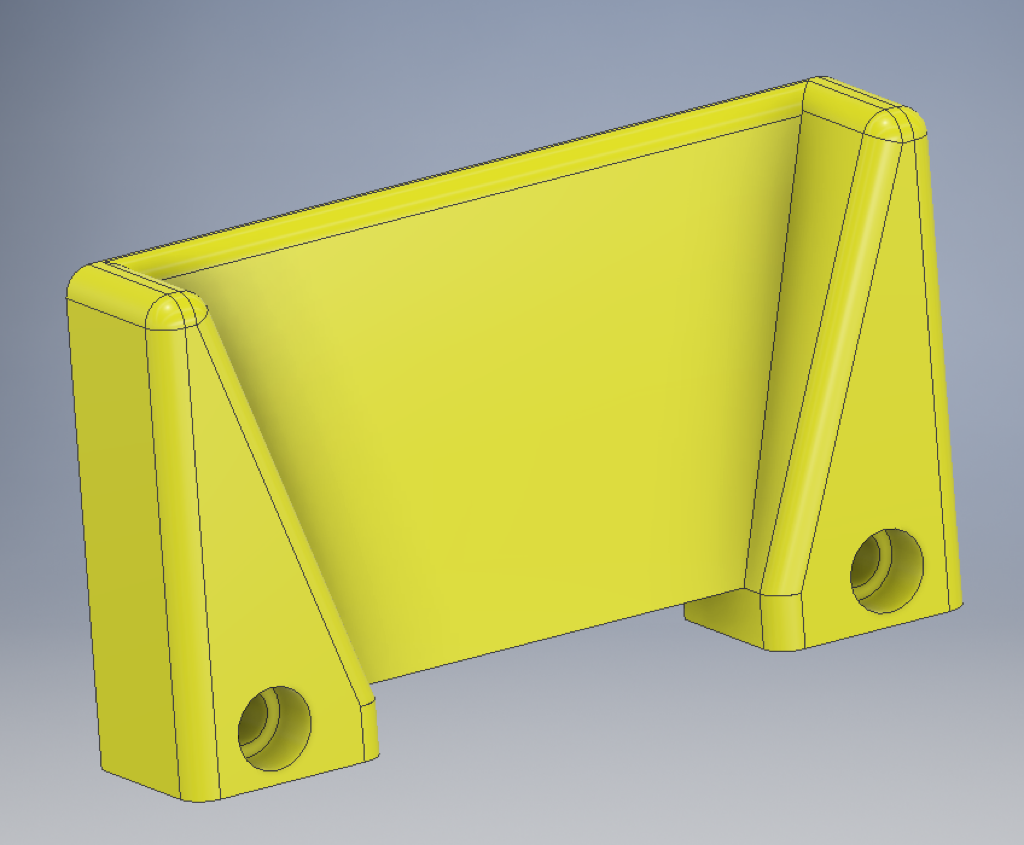
This is the clip I designed to pick up the basket. Both it and the guide would be manufactured out of ABS, which is a fairly strong plastic. I chose it because it is an easy plastic to 3D print, which means it would be very easy to manufacture. I also chose it because it needed to be a little bit compliant, as ABS is at low thicknesses. It is designed so that when the carriage comes down over the basket, the clip flexes with the contour of the guide and then snaps into place underneath the guide. I wanted it to be passive so that the user would not need to fuss with any clasps. This was especially important because a large portion of elderly individuals have poor dexterity.
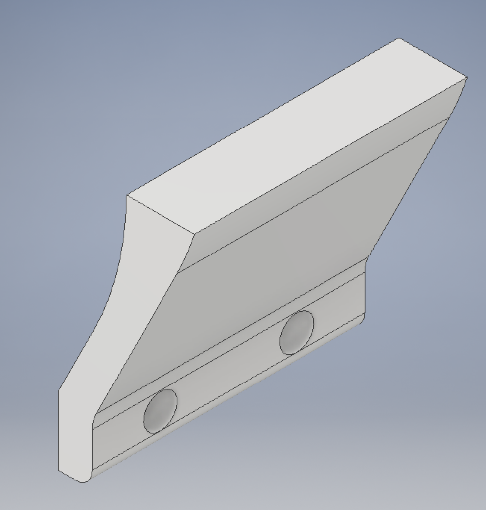
This is the glip guide that attaches to the basket. I designed it to have a wide opening that tapers in so that lining up the clips with the guides was easier. The top opening is about an inch wider than the bottom, so the user has a much bigger gap to aim for. This could be made even larger if it were found to be too small.
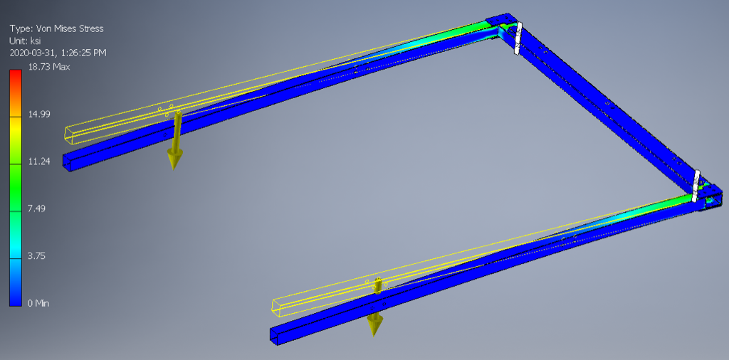
This is the FEA I ran on the crossbar. I applied 25lbs of force downward where the two yellow arrows are. This location is where the front two cart clips are located. The blue sections indicate areas where the material is far from failing. The closer to red the colour gets, the closer that specific area is to failing. The most red part is the area that is nearest to failing. The above image shows what amount of stress each area is experiencing. The units are in ksi, which is 1000lbs per squre inch. So the maximum stress, which is where the crossbar meets the arms, is about 18.73 ksi. The yield strength for aluminum 6061-T6 is about 40 ksi, which is more than twice as much as 18.73 ksi.So even at the reddest area, this carriage still won’t fail. This is better visualized in the picture below.
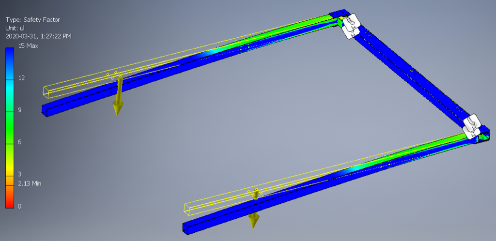
This image is showing the safety factor in each area. The blue areas have a safety factor of 15, which means that the yield strength of the material is 15 times greater than the stress those areas are experiencing. This means these areas will not fail. Safety factors less than 1 indicate areas that will fail. In this image, on the left you can see that the bar shows a minimum safety factor of 2.13. This is greater than 1, so what we saw above is true. Even in the reddest areas, the carriage won’t fail.
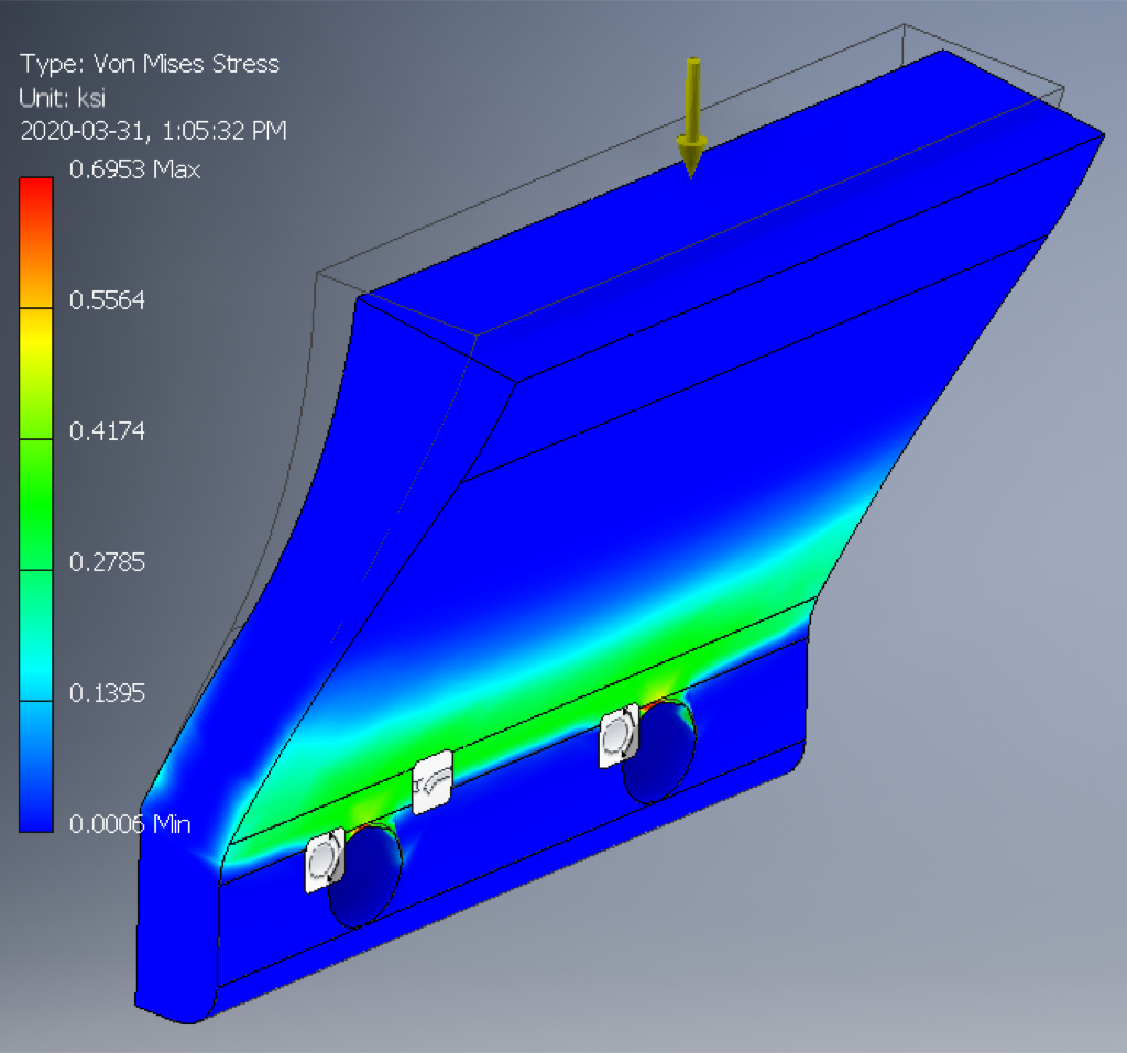
The FEA I ran on these clips was almost identical to the carriage above. The yellow area shows the location where I applied 12.5 lbs of force. Again, the bluest areas are areas where hardly any stress is experienced. The reddest area is at the very top edge of the hole for the bolt. The maximum stress is experienced here and is about 0.7 ksi or 700 psi. The yield strength of ABS ranges between 3-7 ksi, which is far greater than 0.7 ksi.
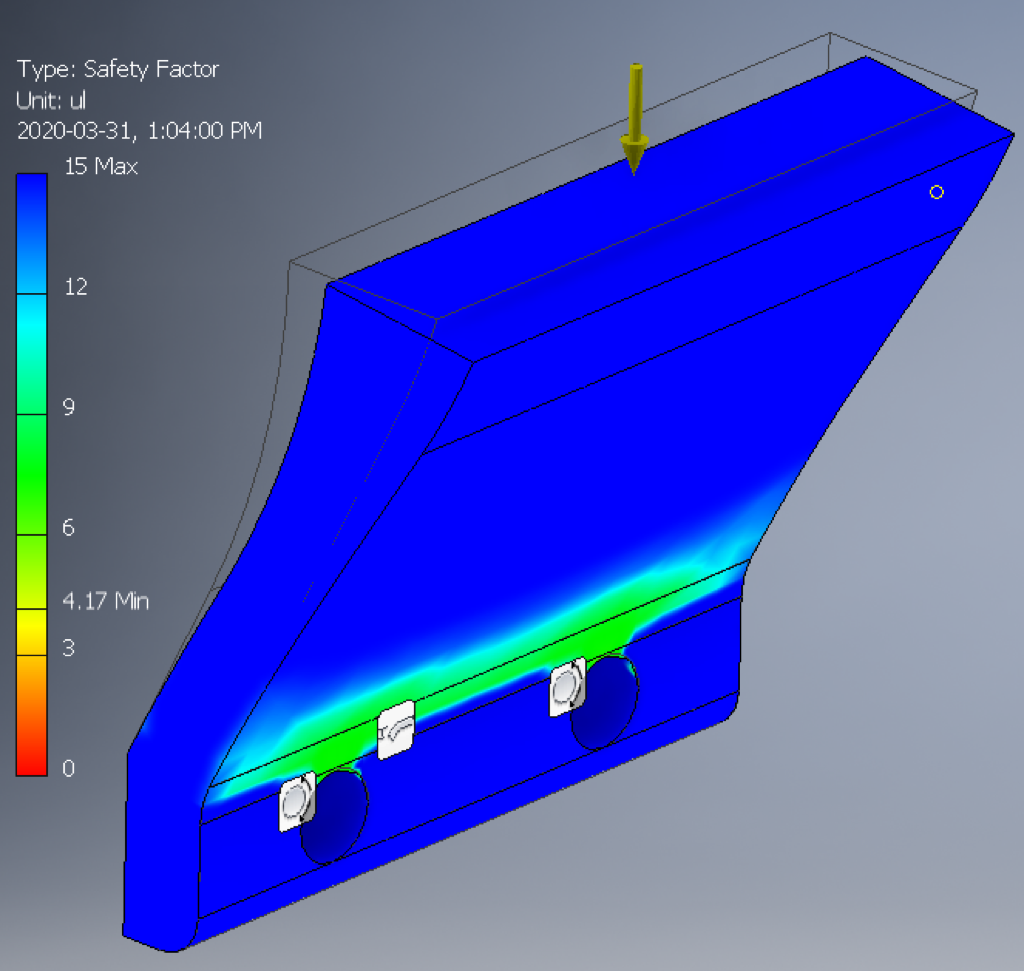
Here you can see that what I said above is correct. The minimum safety factor, at the same location around the top of the bolt hole, is 4.17. 3 ksi is about 4 times greater than 0.7, so this factor of safety makes sense. This clip will not fail under a normal, expected load.”